Mikrotik CCR2004-1G-2XS-PCIe 简单带宽测试
CCR2004-1G-2XS-PCIe是一个有趣的设备,准确的讲它是一个“PCIe网卡形式的路由器”,与普通路由器不同的是,它除了挡板上的两个SFP28 25G网口和一个RJ45千兆管理口这些“物理网口”,其还通过PCIe 3.0 x8有着4个直连主机的25G虚拟网络接口,在主机看来,这相当于4个固定直连到路由器上的“普通”网络接口;而与一些Smart NIC不同的是,CCR2004-1G-2XS-PCIe并不能为主机提供任何offload功能,RDMA和sr-iov等功能应该也是不支持的,它也没有内置交换机芯片,所有从主机到物理网口的数据都需要CCR2004-1G-2XS-PCIe的CPU来转发,换句话说,如果你只是把它当网卡用,那它还不如普通网卡,它的合理用途应当是组成一个服务器和路由器的All-in-one方案。不过无论是作为“集成路由器”还是“普通网卡”的用途都值得我们实践测试一下,这便是这篇文章接下来的部分。
由于没有25G环境,本文在10G内网下测试,CCR2004-1G-2XS-PCIe通过SFP+ DAC连接至CRS305 10G交换机上,交换机上的另一台机器使用x540双万兆电口网卡。CCR2004-1G-2XS-PCIe被安装在一台Core i9-10850k迷你主机(以下简称为host)的PCIe 3.0 x16槽上(CPU直连通道),系统为Fedora Workstation 36。
在host上的一些关于此设备的信息节选:
# lspci
01:00.0 Ethernet controller: Qualcomm Atheros AR8151 v2.0 Gigabit Ethernet
01:00.1 Ethernet controller: Qualcomm Atheros AR8151 v2.0 Gigabit Ethernet
01:00.2 Ethernet controller: Qualcomm Atheros AR8151 v2.0 Gigabit Ethernet
01:00.3 Ethernet controller: Qualcomm Atheros AR8151 v2.0 Gigabit Ethernet

# dmesg
[    1.971577] atl1c 0000:01:00.0: enabling device (0000 -> 0002)
[    1.994014] atl1c 0000:01:00.1: enabling device (0000 -> 0002)
[    2.014003] atl1c 0000:01:00.2: enabling device (0000 -> 0002)
[    2.034983] atl1c 0000:01:00.3: enabling device (0000 -> 0002)
[    2.057479] atl1c 0000:01:00.1 enp1s0f1: renamed from eth1
[    2.073979] atl1c 0000:01:00.0 enp1s0f0: renamed from eth0
[    2.090921] atl1c 0000:01:00.2 enp1s0f2: renamed from eth2
[    2.105991] atl1c 0000:01:00.3 enp1s0f3: renamed from eth3
[    8.700933] atl1c 0000:01:00.0: atl1c: enp1s0f0 NIC Link is Up<25000 Mbps Full Duplex>
[    8.703098] atl1c 0000:01:00.1: atl1c: enp1s0f1 NIC Link is Up<25000 Mbps Full Duplex>
[    8.705370] atl1c 0000:01:00.2: atl1c: enp1s0f2 NIC Link is Up<25000 Mbps Full Duplex>
[    8.707589] atl1c 0000:01:00.3: atl1c: enp1s0f3 NIC Link is Up<25000 Mbps Full Duplex>

# ethtool enp1s0f0
Settings for enp1s0f0:
	Supported ports: [ TP ]
	Supported link modes:   10baseT/Half 10baseT/Full
	                        100baseT/Half 100baseT/Full
	Supported pause frame use: No
	Supports auto-negotiation: Yes
	Supported FEC modes: Not reported
	Advertised link modes:  Not reported
	Advertised pause frame use: No
	Advertised auto-negotiation: Yes
	Advertised FEC modes: Not reported
	Speed: 25000Mb/s
	Duplex: Full
	Auto-negotiation: on
	Port: Twisted Pair
	PHYAD: 0
	Transceiver: internal
	MDI-X: Unknown
	Supports Wake-on: pg
	Wake-on: d
        Current message level: 0x0000003f (63)
                               drv probe link timer ifdown ifup
	Link detected: yes

# ethtool -i enp1s0f0
driver: atl1c
version: 5.17.9-300.fc36.x86_64
firmware-version:
expansion-rom-version:
bus-info: 0000:01:00.0
supports-statistics: no
supports-test: no
supports-eeprom-access: no
supports-register-dump: yes
supports-priv-flags: no
可以看出其在Linux下使用atl1c驱动,连接速度和功能正常,但lspci下型号识别是有问题的。
交换性能测试(“软交换机”模式)
这个模式下所有接口都在一个bridge中,在host上只启用第一个虚拟网口,一个SFP28口接入房间交换机。remote为房间交换机上的主机。测试线路的带宽上限是10G,这里使用iperf3进行测试,也就是大包测试,RouterOS的Fast Forward为默认的开启状态。
| 测试 | 描述 | 带宽 | CPU占用 |
| #1 | 单向host -> remote | 9.39 Gbits/sec | 15% |
| #2 | 单向remote -> host | 9.41 Gbits/sec | 30% |
表格中的CPU占用指CCR2004-1G-2XS-PCIe的,默认RouterOS是开启bridge的Fast Forward,手动关闭后的结果没有明显变化。
路由+NAT性能测试(“集成路由器”模式)
这个模式下,模拟常见的家用路由器环境,但WAN侧使用DHCP,通过一个SFP28接口接入房间交换机,从上级路由器获得地址,remote主机也在房间交换机上。其余接口在一个bridge中,为LAN侧。像普通家用路由器一样,LAN侧有自己的地址段,打开DHCP服务器,开启WAN上的NAT masquerade。
首先是开启Fast Path时的性能:
| 测试 | 描述 | 带宽 | CPU占用 |
| #1 | 单向host -> remote | 9.35 Gbits/sec | 21% |
| #2 | 单向remote -> host | 9.37 Gbits/sec | 31% |
然后是关闭Fast Path时的性能:
| 测试 | 描述 | 带宽 | CPU占用 |
| #1 | 单向host -> remote | 9.37 Gbits/sec | 28% |
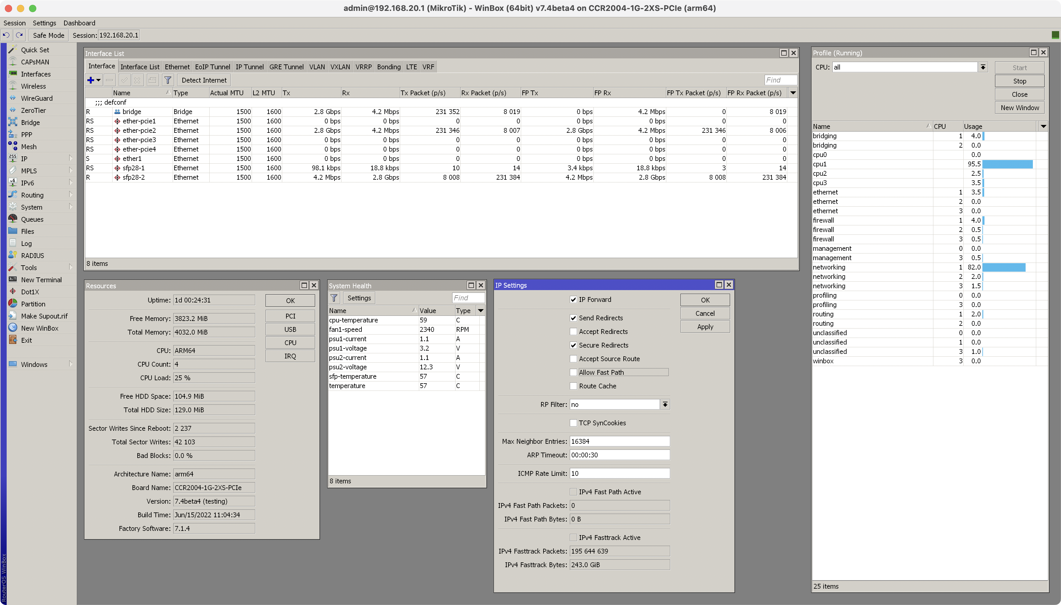
| #2 | 单向remote -> host | 2.80 Gbits/sec | 29% |
可以看到在关闭Fast Path后,remote -> host,也就是WAN to LAN方向的性能不佳。虽然此时CPU占用率并未达到100%,但一共4个核心中,仅有一个核心使用率接近100%,估计是有单核瓶颈,此时的CPU占用情况如下:
